Specification Sheet
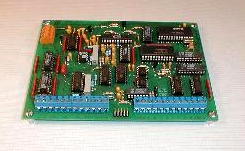
MODEL 202 24-BIT DATA ACQUISITION SYSTEM
zoom
download
Manual
.rtf
.pdf
Sample applications
Application Guidance
updated 10-26-15
Source code
(with sample applications)
The Model 202 is identical to the Model 201 with the following exceptions
Power requirement +/- 12VDC at 80 milliamps (no sleep mode).
There are 2 (not 8) digital inputs.
The connectors are screw terminal type except the serial connector which is a 10-pin header with extension cable.
The filter cut-off frequency is fixed (usually 500 Hz).
The digital outputs are buffered by gain-of-one amplifiers.
Size is 6.5 x 4.8 x 1 inches.
Two DACs have been added. Resolution is programmable up to 16 bits. Settling time increases with resolution. It is 3 seconds at 14 bits.
DACs A & B are wired to input channels 4 and 5 respectively.
PINOUT
x
+12VDC
x
GROUND
x
-12VDC
Analog inputs
Analog out
Digital outputs
Dig-Inp
+
-
+
-
+
-
+
-
G
TP
G
G
G
RS
1
1
2
2
3
3
4
4
D
1
2
D
D
D
A
B
C
D
E
F
G
H
1
2
x
x
x
x
x
x
x
x
x
x
x
x
x
x
x
x
x
x
x
x
x
x
x
x
if pinout description above is displayed incorrectly in your browser
click here
Subtract 1 from analog and digital input labels for addressing. For example, analog input channel 0 is labeled input 1.
Only the 2 least significant bits of the digital input word are used.
The sleep command is not valid.
The filter command is deactivated.
The lower 4 bits of the control register are now used as DAC controls.
Command token 7 is now used to load the DAC counter registers.
Details for loading the DACs are found at the end of the driver source listing. The driver uses a "Z" keypress to access the DACs.
In scanning mode, the external control code must be 8 to enable the DACs. Use external code 0 to disable the DACs.
There is no expansion connector.
HOME
Contact us for sales or technical assistance
lawsnlab@lawsonlabs.com
© Lawson Labs Inc. All rights reserved