|
|
|

Other precision data
acquisition products
|
Other precision data acquisition products |
|
||||||||||||||||||||||||
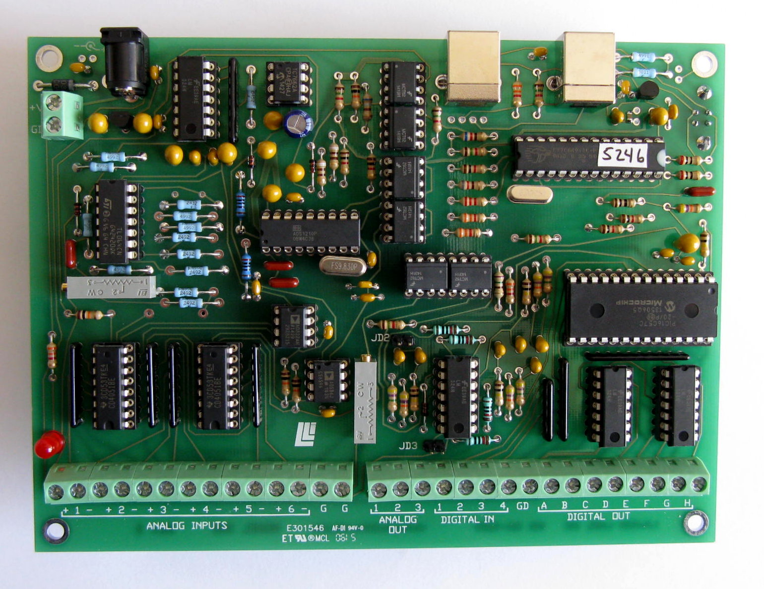
The digital input word is updated with each conversion in polled mode, with each packet of ten conversions in normal scanning mode, or with each conversion in digital input scanning modes. The digital inputs are active low. They can be activated by a contact closure to digital ground or by any 5 volt logic signal referenced to the same ground. The digital input word is displayed as an integer between 0 and 255. You may want to view it in binary format so that individual inputs show as ones and zeros. The digital output command puts a latched 8- bit digital word at terminals A through H on the input/output connector. Valid values are in the range of 0 to 255. The digital outputs are buffered to source or sink 20mA. Note that when sinking current, the voltage may rise significantly above 0 volts. Because of the extreme resolution possible with the Model 302 it is necessary to carefully shield your input signals from electrical noise. Electrical noise can be radiated through the air and picked up by wiring and/or circuitry. It can also be introduced via the power connections. Also, air currents can create sufficient temperature changes to cause thermal noise. 25-PIN CONNECTOR PINOUT (analog)
Other Input/Output Connector (16 terminals)
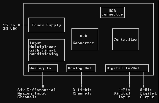
Note: For maximum protection, any unused input terminals should be connected to ground. This is done to protect the circuitry from static discharges which can be of extremely high voltage. Open inputs can also pick up noise. Strain-relief is recommended for all permanent wiring on the connector. Otherwise, physical stress may cause the failure of an electrical connection. The connector hood provided has a strain-relief clamp. MODEL 302 BLOCK DIAGRAM
back to table of contents |
||||||||||||||||||||||||||||||||||||||||||||||||||||||||||