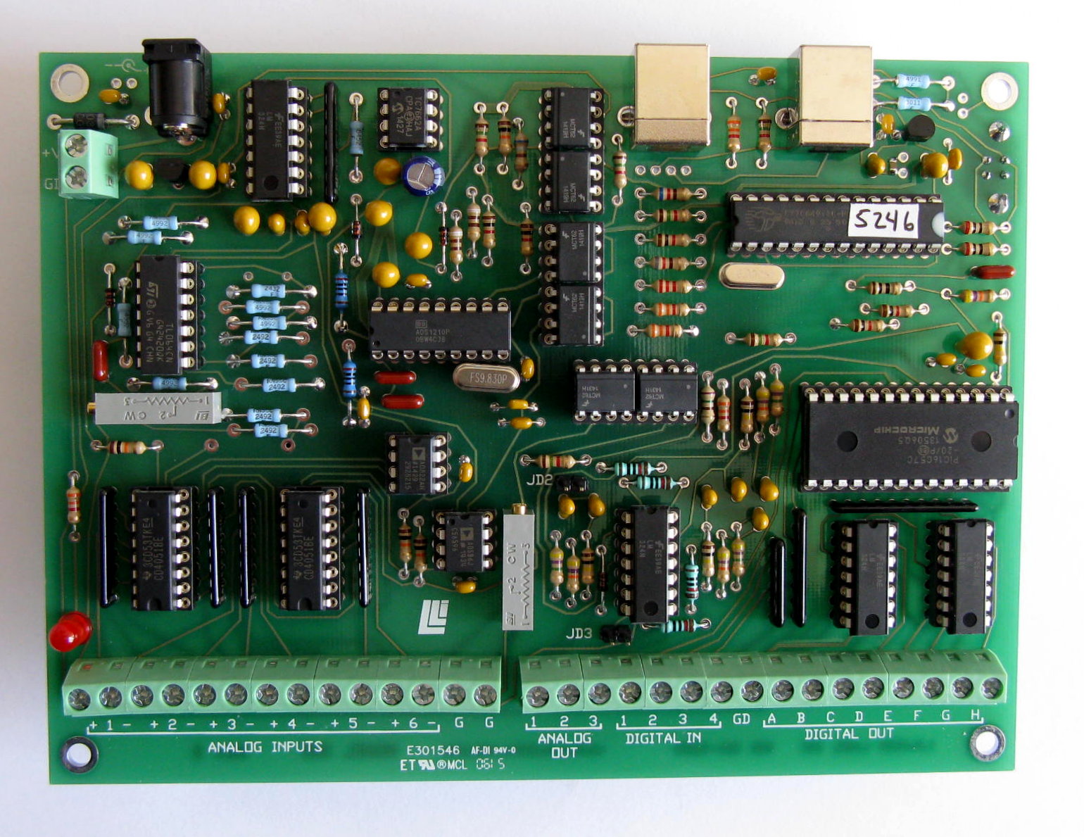
A battery is a convenient voltage source for checking the Model 302. Connect the positive and negative ends of the
battery to a pair of positive and negative analog input terminals on the analog input connector. You will also need a wire from one
end (normally the negative) of the battery to ground at the Model 302 to insure that the input voltage at both input terminals is
within 6.5 volts of ground. Several ground terminals are provided for the purpose. This third wire ground is for common-mode
requirements only, and, while necessary, it is non-critical. Remember that the Model 302 is optically isolated and floats in
comparison to the computer chassis ground. A typical D cell should read about 1.5 volts. Reverse the wires and note the polarity
change. Connecting the input wires directly together will cause a potential of zero volts. An open circuit will read
unpredictably. A positive overvoltage will read 5 volts. A negative overvoltage will read -5 volts. The analog input
channels are protected against continuous overvoltage up to 60 volts.
Because of the extreme resolution possible with the Model 302 it is necessary to carefully shield your input signals from
electrical noise. Electrical noise can be radiated through the air and picked up by wiring and/or circuitry. It can also be
introduced via the power connections. Also, air currents can create sufficient temperature changes to cause thermal noise.
25-PIN CONNECTOR PINOUT
|
+1
|
-1
|
+2
|
-2
|
+3
|
-3
|
+4
|
-4
|
+5
|
-5
|
+6
|
-6
|
GD
|
GD (ground)
|
|
|
Other Input/Output Connector (16 terminals)
|
Analog Out
|
|
Digital In
|
|
Digital Output
|
|
1
|
2
|
3
|
|
1
|
2
|
3
|
4
|
|
GD
|
A
|
B
|
C
|
D
|
E
|
F
|
G
|
H
|
|
|
Note: For maximum protection, any unused input terminals should be connected to ground. This is done to protect
the circuitry from static discharges which can be of extremely high voltage. Open inputs can also pick up
noise. Strain-relief is recommended for all permanent wiring on the connector. Otherwise, physical stress may
cause the failure of an electrical connection. The connector hood provided has a strain-relief clamp.
MODEL 302 BLOCK DIAGRAM
back to table of contents
|


