|

|
|

Other precision data
acquisition products
|

Other precision data acquisition products |
|
||||||||||||||||||||||||
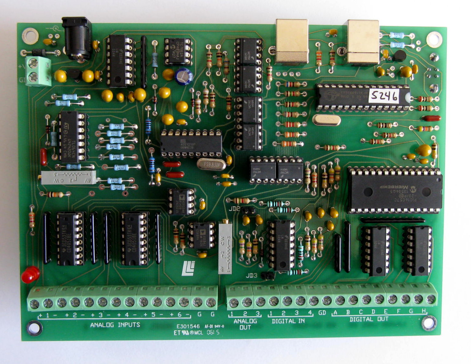
The Model 302 features fully differential inputs. A basic understanding of differential measurements will help you to use your card to best advantage. The plus and minus input pins should be wired directly to the voltage being measured. In this way, it is assured that the only current flowing in the wires will be the input current of the A/D converter. Because the wires have finite resistance, any current flowing will cause a voltage drop and a corresponding error. The Model 302 requires a vanishingly small input current so the error caused by even very long wires is negligible. For proper operation it is necessary that the positive and negative inputs both be within 6 volts of ground. For a floating voltage source, this is generally accomplished by connecting a third wire between the Model 302 ground and a ground terminal at the source of the measured voltage. Ground currents may flow in this wire, but the resulting voltage drop will not cause a measurement error. Redundant grounding can cause ground loops. Ground loops can cause erratic behavior because currents will flow through different paths at different times causing unpredictable voltage drops. TYPICAL INPUT CONNECTIONS
Best results are obtained with filtered, buffered voltages. Electrical noise travels through the air and can be picked up by interconnecting wires. The first defense against noise is shielding. Use shielded wire with the shield connected at one or both ends to ground. (See above.) The lower the impedance of the voltage source, the less susceptible the wiring will be to electrical noise. If noise problems persist, try to locate the source of the interference and shield it. Electric motors, electric heaters and flickering fluorescent lights are potential sources of interference.
Settling time is the time in milliseconds required to obtain a fully valid reading after an instantaneous full-scale step Effective resolution is defined as total resolution minus RMS noise. Numbers above use an oversampling factor of four. See the FuncDesc.doc file and the sample application source code for programmer's information. We will continue to add operating system and language support for the Model 301 as appropriate. back to table of contents |