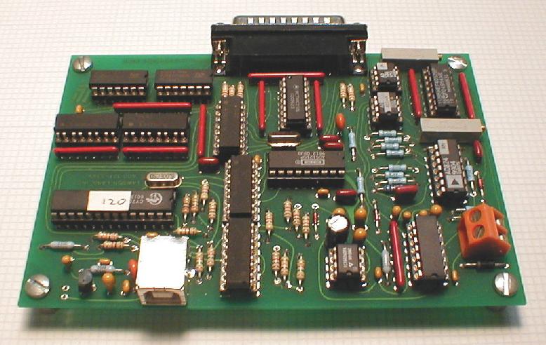
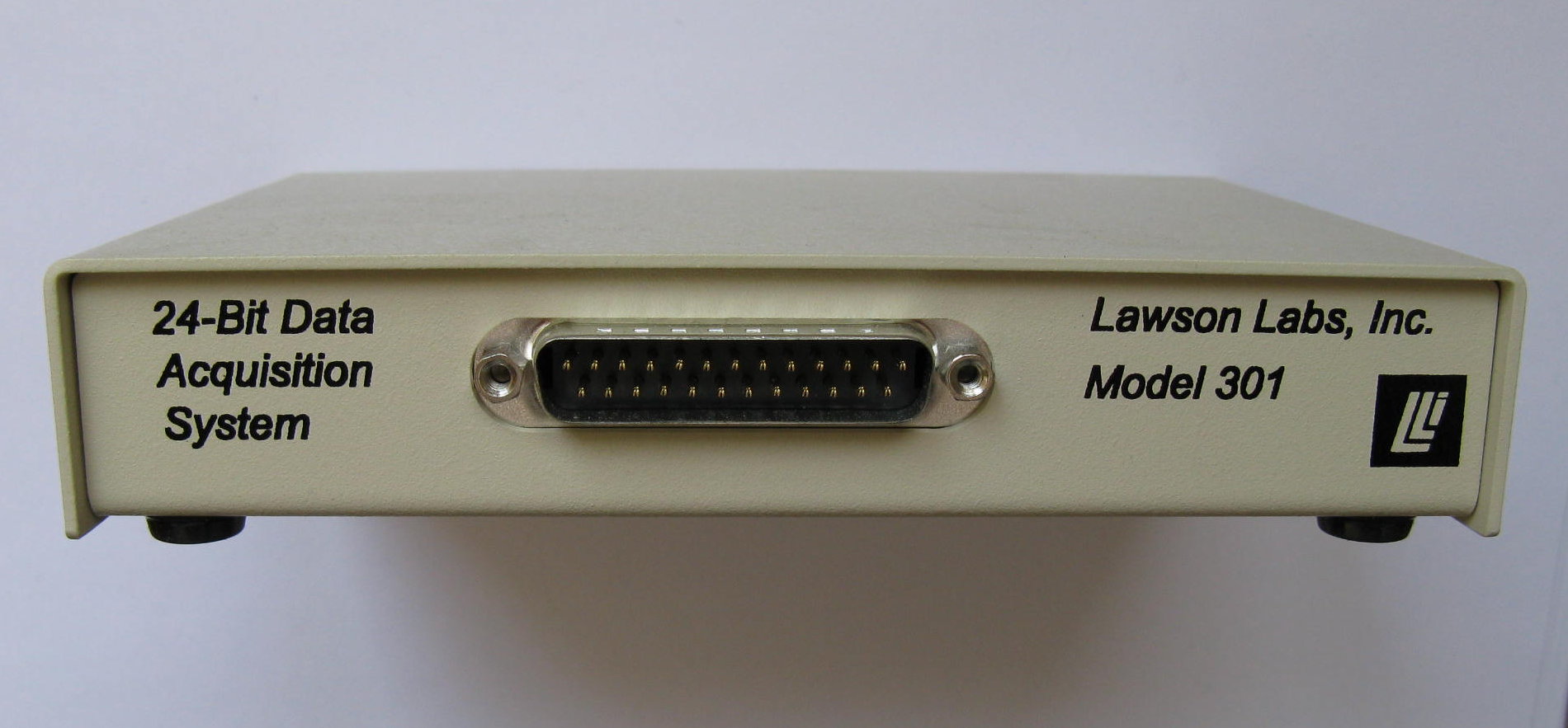
25-PIN CONNECTOR PINOUT
|
PIN 13
|
Digital Ground
|
|
|
|
|
|
PIN 25
|
Digital Out 7
|
|
PIN 12
|
Digital In 0
|
|
|
|
|
|
PIN 24
|
Digital Out 6
|
|
PIN 11
|
Digital In 1
|
|
|
|
|
|
PIN 23
|
Digital Out 5
|
|
PIN 10
|
Digital In 2
|
|
|
|
|
|
PIN 22
|
Digital Out 4
|
|
PIN 9
|
Digital In 3
|
|
|
|
|
|
PIN 21
|
Digital Out 3
|
|
PIN 8
|
Digital In 4
|
|
|
|
|
|
PIN 20
|
Digital Out 2
|
|
PIN 7
|
Digital In 5
|
|
|
|
|
|
PIN 19
|
Digital Out 1
|
|
PIN 6
|
Digital In 6
|
|
|
|
|
|
PIN 18
|
Digital Out 0
|
|
PIN 5
|
Digital In 7
|
|
|
|
|
|
PIN 17
|
Digital Ground
|
|
PIN 4
|
Digital Ground
|
|
|
|
|
|
PIN 16
|
Analog Ground
|
|
PIN 3
|
Analog Ground
|
|
|
|
|
|
PIN 15
|
CHANNEL 1+
|
|
PIN 2
|
CHANNEL 1-
|
|
|
|
|
|
PIN 14
|
CHANNEL 0+
|
|
PIN 1
|
CHANNEL 0-
|
|
|
|
|
Note: For maximum protection, any unused input terminals should be connected to ground. This is done to protect
the circuitry from static discharges which can be of extremely high voltage. Open inputs can also pick up noise.
Strain-relief is recommended for all permanent wiring on the connector. Otherwise, physical stress may cause the
failure of an electrical connection. The connector hood provided has a strain-relief clamp.
back to table of contents
|