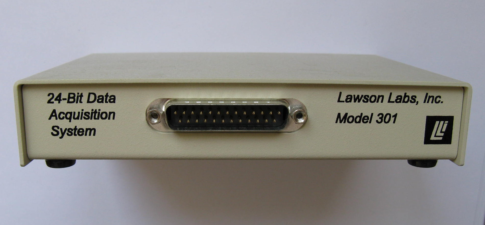
The Model 301 interconnections consist of a DB25 cable
connector, a USB connector, and a 2-terminal power connector
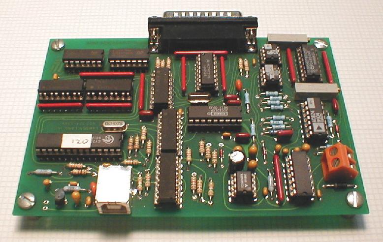
NOTE: Always handle circuit cards by the edges. Static
electricity can damage computer circuitry, so care
should be taken to control static discharge.
For operational checks, only the power supply and serial cable need be connected. The power supply
voltage can range from 9 to 15 VDC and does not need to be regulated. Power is connected to the terminals on the orange
terminal block. The power terminals are labeled "+" and "-". The wall-mounted transformer supplied has a white stripe on
the positive wire. A battery, or other DC supply (in the correct voltage range), can be substituted. The board is protected
against reverse voltage but will not operate without a properly connected supply. The power can be connected before or after
the serial interface connection is made. Note that the computer chassis ground is not connected to ground at the Model 301
because of the optical isolation. If your Model 301 has been mounted in the standard enclosure it will have a 47K ohm resistor
placed between the computer's ground and the Model 301's chassis ground. This resistor should be removed if the two grounds
are to be more than 100 volts apart. (Contact the factory for details.)
For maximum accuracy the board should be enclosed in the shielded box. Open cell is placed against both
sides of the board to minimize air currents. Although a copper/solder junction is not considered a good thermocouple, there
are many such junctions and collectively, they can have an effect on the least significant bits.
-
FIGURE 1:
MODEL 301 BLOCK DIAGRAM
The software drivers provided include a system-level
USB driver, a DLL and sample application code, with source,
in VC or VB. Win98 and Win2000 are supported. Refer to the
read_1st.txt file on the disk before installing the
drivers. Do not forget to follow the steps described there for
adding your Model 301's ID number to the device list. The latest
version of the driver software and sample application code can
be downloaded at no charge from lawsonlabs.com. In some cases,
an updated microcontroller chip may be required to take advantage
of new features.
|